Here are the final deliverables for the CIS 565 final project.
Live code:
http://iamnop.com/raymarch/
Code
https://github.com/nopjia/WebGL-RayMarch
Slides
https://dl.dropboxusercontent.com/u/5058905/raymarch/presentation.pdf
Report
https://dl.dropboxusercontent.com/u/5058905/raymarch/report.pdf
Video (turn on captions)
http://www.youtube.com/watch?v=djTVUUJvC9E
Wednesday, April 25, 2012
Tuesday, April 24, 2012


Sunday, April 22, 2012
Another Experimental Feature
Decided to throw in another fun experimental feature.
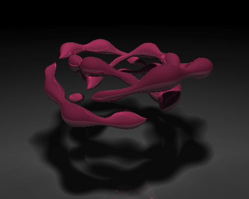
The Displaced Bumps option displaces the distance function according to an arbitrary function (in this case a simple sin wave). It doesn't work very well with square shapes. However, it works great with round box, and it creates a very interesting shape with the knot.


The Displaced Bumps option displaces the distance function according to an arbitrary function (in this case a simple sin wave). It doesn't work very well with square shapes. However, it works great with round box, and it creates a very interesting shape with the knot.
Coding Done! (for now)
Worked straight 10 hours today. I think I have reached a point where I am satisfied with the code.
A huge improvement is a user interface for selecting options. To bring up the GUI, press "Shift+Q". The code is live at www.seas.upenn.edu/~pjia/raymarch (since unfortunately iamnop.com is still having issues.) If you are running this, remember to resize your browser to a smaller size for reasonable performance.
Here's what it looks like now:
Aside from fixing corner cases and doing optimizations, here are the new features implemented:
- New GUI! (of course!)
- Mirrored reflections.
- New more realistic soft shadows method, based on technique by the.savage.
- New fog. Not really fog anymore. It simply darkens the color relative to distance marched. Takes care of the far distances where numerical errors are large.
- Focal blur, which is basically dithering based on distance. This is implemented last minute and doesn't produce very good results.
And of course, the project is not complete, and there are a few known bugs:
- Ambient Occlusion and Subsurface Scattering stops working when warping is turned on.
- As mentioned, focal blur at this moment is an experimental and unfinished feature. To improve, I will need to take several dithered samples and average between them. However, this will hurt performance.
- The quaternion fractal does not render quite well with all modes, since I'm trying to optimize across all types of scenes, balancing quality and performance. The current smoothing level doesn't work quite well for the fractal, so there will be breaks in the surface. It's also running at a few iterations, so it seems to leave artifacts across the scene. I'm just putting it in there as an example of a very complex shape.
Saturday, April 21, 2012
Distortion Issue Solved!
Distortion issue is caused by the inaccuracies of the ray marching method. The distance based marching does not provide a good enough approximation of the shape.
The solution is to apply a "smoothing" constant having a value between 0.0 to 1.0. This number is simply scales the distance estimated sampled at every step, such that the ray will only march a certain % of the distance. So no smoothing would be 1.0, stepping the whole distance towards the scene.
This is a balance between quality and performance. Smoothing eliminates the rippling distortion effect. However, now that we're taking a non 100% of the distance sampled, we need to take more steps in order to reach the scene.
The suggested smoothing level is 0.5, but I'm afraid performance would take a hit since now I'll have to take many more steps in order to render the edge details. A good number that I empirically came up with is 0.75, meaning the ray march would only march 75% of the distance closest to the scene.
Below are examples:
The twisted cube. Smoothing at 0.75.
Some minor rippling effect still visible at lower left corner, but is much better.
The Julia quaternion fractal. Smoothing 0.5.
Now smooth everywhere compared to before where there were gaps in the surface.
Distortion Issue
The distortion issue becomes worse when trying to render increasingly complicated objects.
Just as a test, I ported another shape form the.savage's renderer, the Julia quaternion fractal. It was able to run at ok performance at few iterations of the fractal. However, the distortion problem becomes lot worse and the shape is barely viewable.


At this point, I would like to shift the focus from the actual modeling of fractals back to the rendering. I have been trying to read up on fractals but the math is making it a very difficult and a slow process, and right now I still don't have a good understanding.
Since now I don't have too much time left, I'd rather focus on the renderer and its performance, especially since I have just discovered there's much performance yet to be squeezed out (see last post.) I also have a few more effects that I would like to implement, such as glow, reflection, real soft shadows, and focal blur.
I feel that going in this direction is much more relevant to this class than trying to construct fractals. Going forward, instead of trying to generate my own fractals, I would port existing fractal code from various resources as test target renders.
Just as a test, I ported another shape form the.savage's renderer, the Julia quaternion fractal. It was able to run at ok performance at few iterations of the fractal. However, the distortion problem becomes lot worse and the shape is barely viewable.
5 iterations
10 iterations. Shape barely recognizable.
Since now I don't have too much time left, I'd rather focus on the renderer and its performance, especially since I have just discovered there's much performance yet to be squeezed out (see last post.) I also have a few more effects that I would like to implement, such as glow, reflection, real soft shadows, and focal blur.
I feel that going in this direction is much more relevant to this class than trying to construct fractals. Going forward, instead of trying to generate my own fractals, I would port existing fractal code from various resources as test target renders.
Slow Progress + Issues
Worked on the code a bunch today. I'll quickly run through some of the issues.
Implemented the recursive tetrahedral outlined here. However, it is represented in points, and is not appropriate for this framework. So I decided to remove it. Below's a render of the fractal using the number of steps.


Implemented the recursive tetrahedral outlined here. However, it is represented in points, and is not appropriate for this framework. So I decided to remove it. Below's a render of the fractal using the number of steps.
Next was to reverse my last change for the branch optimization that I blogged about. I just did a few tests and realized that when I flip the camera such that it is under the ground plane and it would only render black, I noticed a FPS increase of 2-3. This is because of screen space coherence and warp termination. There is branch diversion during whether it would render or not, and when enough pixels do not need to render, there is a performance increase.
Next I ported a knot shape code from the.savage's renderer from his renderer in GLSL Sandbox. Performance took a huge hit. Result below:
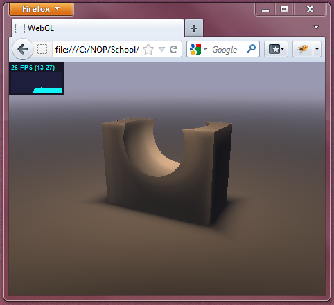
Then I realized that his renderer does something quite smart. He uses a circular bounding volume, and his renderer only renders what is inside the volume. It works for him since he only renders single floating objects in the middle of the screen. I implemented this into my own pipeline. It was a huge performance boost, over double the FPS. And if I zoom out such that the bounding volume occupies a even smaller portion of the screen, I see significant performance increase, from ~18 FPS to up to 90 FPS, again, due to coherency and warp termination. However, this technique is not too suitable for the types of images I'm trying to render since it crops only the center area of the scene. Here's a result:
I'll have to think about whether to use this technique, since it does provide a very significant performance boost.
Next, I discovered that my renderer has a huge issue in that for certain shapes when viewed from certain angles, there are banding / rippling distortion errors. I spent a long time looking at it but still cannot find the answer. I might have to go ahead without solving this issue since time is running out and I'd rather focus on other things. Here's an example:
Thursday, April 19, 2012
Initial Test + Micro Optimization
Implemented Inigo Quilez's menger sponge, by following his tutorial. This is to test if the framework can handle scenes that are getting more complex. The frame rate is still acceptable, on my puny laptop graphics card.

I also implemented a micro optimization that came to my mind. Before I had:
Instead, I use built-in functions to eliminate the branching altogether.
I'm not sure if this helps performance, might be by a difference of 1 fps at the moment.
I also implemented a micro optimization that came to my mind. Before I had:
if (t>0.0) {
// compute col
gl_FragColor = vec4(col, 1.0);
}
else {
gl_FragColor = vec4(0.0, 0.0, 0.0, 1.0);
}
Instead, I use built-in functions to eliminate the branching altogether.
t = max(sign(t), 0.0);
gl_FragColor
= vec4(t*col, 1.0);
I'm not sure if this helps performance, might be by a difference of 1 fps at the moment.
Wednesday, April 11, 2012
So Much Math!
Found a great resource on rendering fractals, written by Mikael Hvidtfeldt Christensen, who is a physicist and a software developer (and apparently an expert on fractals rendering.)
http://blog.hvidtfeldts.net/index.php/2011/06/distance-estimated-3d-fractals-part-i/
He wrote a 7-part (so far) article on rendering fractals. His series is almost a one-stop resource for all things related to rendering fractals, covering topics from coloring and lighting, to complex math associated with generating different types of fractals, such as Julia sets and Mandelbulbs.
Most of the rendering part I have already figured out from various other sources, but it is a great read nonetheless, and has given me a few more ideas on various rendering passes. The part that is most useful is the part on modeling and generating fractals. This opened up a whole new area that I am completely new to. There is a tremendous amount of math involved, and it is a rather difficult read. A lot of the math I do not understand, and I am still working on the reading and figuring it out.
I only wished I had found this blog earlier!
Here are some amazing images from stuff he's working on. This guy's a true expert!
http://www.flickr.com/photos/syntopia/
Tuesday, April 10, 2012
Check Out Live Code!
Quite satisfied with the rendering results. Go to http://iamnop.com/raymarch/ for some nice real-time live code! (Hint: it's animated!)

Observed Performance Difference
With the full shading stack, rendering each frame becomes much more heavy, and performance differences become greater.
From observation, when viewport is mostly sky (far distances), the frame rate is about 30 fps. When the viewport is mostly ground or geometry (close distances), the frame rate jumps to about 50 fps. This is good news, since it implies that the ray marching loop is correctly optimized, where it successfully terminates when an intersection is found. I was not able to observe this difference until now.
From observation, when viewport is mostly sky (far distances), the frame rate is about 30 fps. When the viewport is mostly ground or geometry (close distances), the frame rate jumps to about 50 fps. This is good news, since it implies that the ray marching loop is correctly optimized, where it successfully terminates when an intersection is found. I was not able to observe this difference until now.
Combined Render Passes
I have tweaked and fixed up various shading passes, and I think I am ready to move onto the modeling part of the project.
Here are the components of the shading:
Here's the current output:
Here are the components of the shading:
- Diffuse lighting
- Soft shadows. Used instead of ray traced shadows. Also eliminates the need for ambient occlusion.
- Subsurface scattering (so called). I figured it looks more like effects of depth volume rendering, not quite like subsurface scattering, but can account for some types of a similar effect.
- Fog. Mainly used to hide numerical errors for large distances. Instead of light blue (or other fog color), can be set to black to simulate view-aligned lighting.
Here's the current output:
Thursday, April 5, 2012
Initial Subsurface Scattering
Implemented subsurface scattering based on sample code from Mazapan. The code again is similar to the technique for ambient occlusion. It samples distances along the marching ray. However, since it relies on negative sampled distance, it only works on signed distance fields (for example, it doesn't work with udBox).
Here's an initial result.

Tuesday, April 3, 2012
Soft Shadows
Implemented soft shadows. The technique is very similar to ambient occlusion. Instead of taking samples along the normal at the surface, it takes samples along the ray from the surface to the light. This roughly estimates the distances of the surrounding object to the ray of light, creating an effect very visually similar to soft shadows. Therefore, this is "fake" empirical soft shadows and is purely geometry based.
Here are some results of just the soft shadows component. I personally think they look very nice, and I am questioning the need for the diffuse lighting component at all.


Here are some results of just the soft shadows component. I personally think they look very nice, and I am questioning the need for the diffuse lighting component at all.
Ambient Occlusion
Implemented ambient occlusion, based on method proposed by Iñigo Quilez. The method is originally based on another paper, "Fast Approximations for Global Illumination on Dynamic Scenes."
Here's how the method works: the ambient occlusion coefficient at each surface point is computed by taking samples of the distance field at varying distances above the point long its normal. This essentially estimates the "openness" of the region above the point. Here is a more formal mathematical description:

Here is an output of just the ambient occlusion term.

Here is ambient occlusion with diffused lighting.


Here's how the method works: the ambient occlusion coefficient at each surface point is computed by taking samples of the distance field at varying distances above the point long its normal. This essentially estimates the "openness" of the region above the point. Here is a more formal mathematical description:
Here is an output of just the ambient occlusion term.
Here is ambient occlusion with diffused lighting.
Also, I want to point out that, with ambient occlusion implemented, there is an unintentional "skyline" effect where the ground plane ends. This could be because the ray does not intersect anything and therefore the normal is undefined at those points. However, it does provide a nice gradient visual effect, where before there were curved bands going across as a result of numerical errors. Here's a better picture of the "skyline".
Sunday, April 1, 2012
Subscribe to:
Posts (Atom)